We are a renowned manufacturer and Supplier of Waste Tyre Pyrolysis Plant. We fabricate Waste Tyre Pyrolysis Plant using quality raw material. Our Waste Tyre Pyrolysis Plant is extensively used for the recycling of waste tyres, plastic, rubber and helps in producing fuel like oil, carbon black powder, steel, gas that are high in demand. Waste Tyre Pyrolysis Plant, supplied by us, ensures 100% recycle of waste tires and leaves no residue at the end of the process. Our Waste Tyre Pyrolysis Plant does not require any catalyst during the recycling process and works on a process that is 100% pollution-free and safe.
Attributes:
- Requires a small amount of investment
- High availability of materials
- Short recovery period
- The latest & tried technology with the best price
- Requires less space and manpower
- Energy efficient
Advantages of tyre pyrolysis plants:
- Purest quality of Pyrolysis Oil as the finished product.
- Use of green technology to achieve environment-friendly processes.
- Safety valve (pressure and temperature valve) used to improve safety, profitability & ease of operation.
- It is energy self-sufficient.
- No external fuel is required for heating.
- It recovers energy and generates value from waste, in form of fuel, steel wire, and charcoal.
- Reduces land pollution.
- Eco-friendly recycling of tyres.
- Commercially viable process.
- A good substitution to LDO / Furnace oil
Download Brochure:
PLANT & ITS COMPONENTS
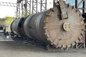
Reactor
- Made from heat resistance Plate.
- Reactor is consider as the heart of this plant
- Raw material feed inside will start converting to gas at 300-350 degree Celsius
- Anaerobic heating process takes place.
Tanks
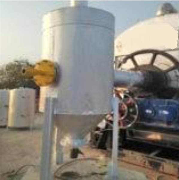
A) Gas Tank
- It is also called gas separator tank because gas obtained by heating raw material from reactor will get separate here .
- Hence oil produce will store in the bottom of tank and gas will move further to water coolant pipe
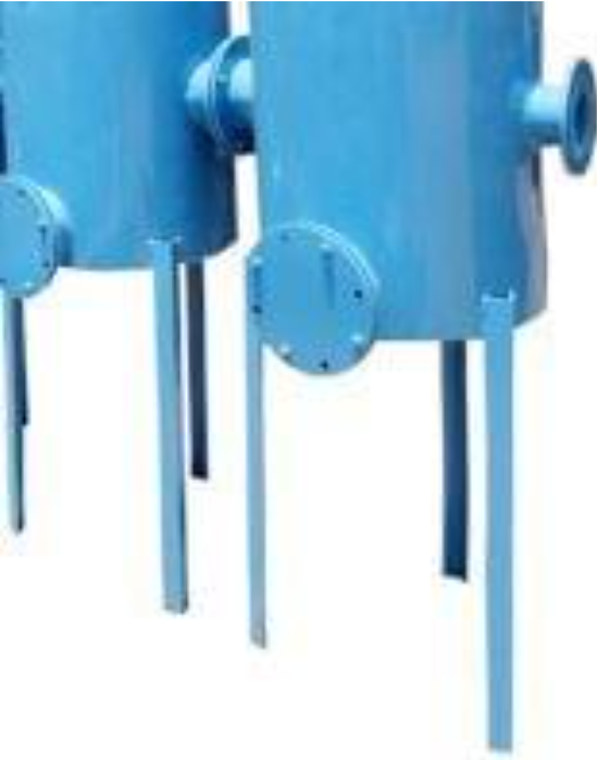
B) CARBON HOLDING TANK (2 NOS)
- Carbon holding tank which is in water seal tank in this tank oil and carbon will mix well and will move to pipe condenser and carbon particles will set down.
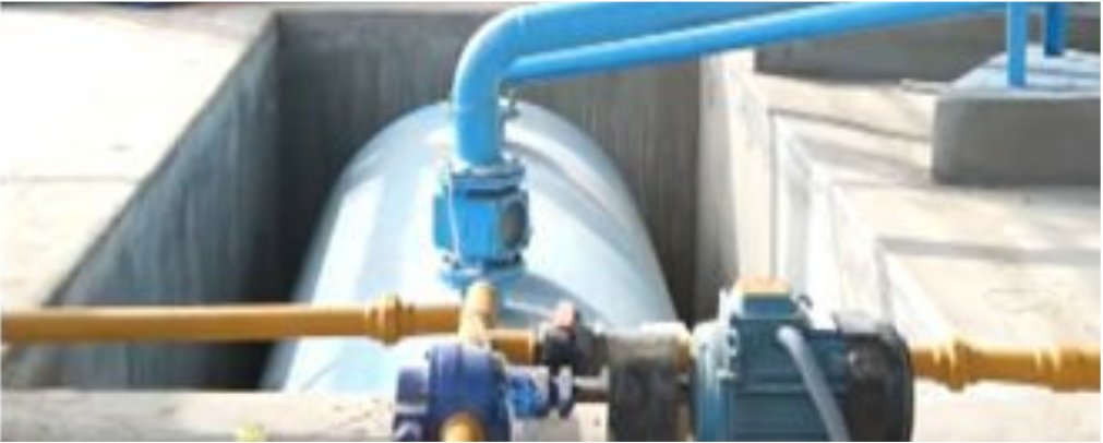
C) UNDERGROUND OIL TANK
- Should Be 40% Oil Store In This Tank.
- Light Gas Transfer To Gas Tank From This Under Ground Oil Tank.
CONDENSING SYSTEM
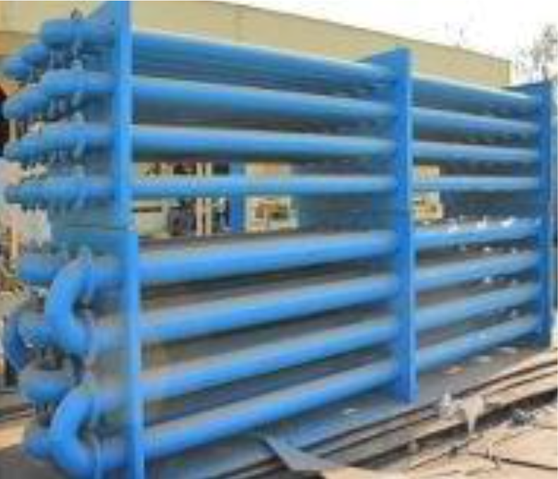
A) CONDENSING PIPE
- This pipe is very useful to increase Yield Percentage.
- It is usually designed in zigzag pattern, so it creates huge condensing area.
- Very easy to maintain.
- Condenser is coil type.
- The more the coils faster the cooling process. Hence more yield percentages obtained.
- Continuous water supply converts condensed vapor into oil, which is transferred into oil receiving tank and the uncondensed gas travels to the next level.
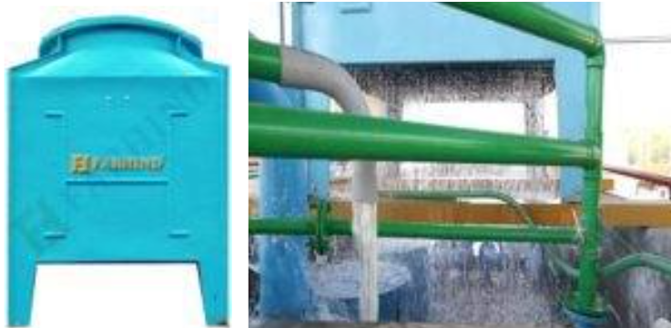
B) COOLING TOWER
- It has 70 TR capacity.
- It is very useful for cooling of hot vapors to oil.
- It convert hot water to cold water by circulation.
CHIMNEY & BLOWER
SMOKE CHIMNEY (100 FEET)
- Smoke chimney is connected to wet scrubber system
- Black smoke is converted to white smoke via scrubber system which will be
- released through chimney into air.
- It is of 100 FT so that pollution is prevented into air.
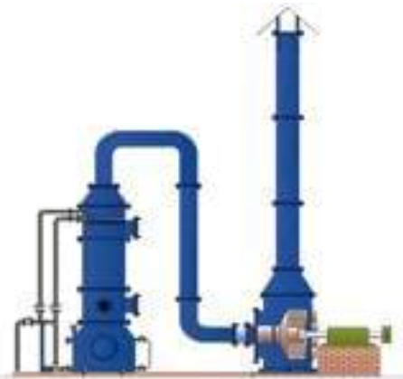
WET SCRUBBER SYSTEM
- It consist of water sprinklers inside the pipe.
- Polluted smoke coming from the process is continuously sprinkled by water.
- Hence carbon gets settle down at the bottom of the tank & white smoke will
- be released through chimney.


Pingback: Waste Tyre Recycling: Transforming Challenges into Solutions – Kay Iron
Pingback: The Future of Tire Recycling: Exploring Innovations in Pyrolysis Machinery – Kay Iron
Pingback: How Waste Tyre Pyrolysis Plants are Revolutionizing India’s Waste Management – Kay Iron
Pingback: Tyre Pyrolysis Plant Manufacturers & Suppliers in Haryana - Kay Iron Works